Input variables
Generic variables
These variables can be found in virtually all reports as input variables
- Design Pressure – Pc
- Pressure assumed to be present in the component according to the design terms
- Design Temperature – T
- Temperature assumed to be present in the component according to the design terms
- Material (header/branch)
- Name of selected material used for the construction of the component
Specific variables
These variables are component specific
- Outside Diameter header and branch – Do, do
- Outside diameter of the attached part. The diameter runs from the outside of the wall to the opposite outside of the wall, through the center of the circle. Generally the branch is smaller in diameter than the header.
- Nominal Thickness header, branch and reinforcement – esn, ebn, epln
- Thickness ‘as is’, meaning it is the design thickness taking into account corrosion and tolerance.
- Corrosion header and branch – c0s, c0b
- Amount of thickness that accounts for the possible effects of corrosions.
- Tolerance header, branch and reinforcement – c1s, c1b, c1pl
- Tolerance in thickness for production
- Joint coefficient header and branch – zs, zb
- Effectiveness of the strength, depending on whether joints are seamless, welded, or expected to perform worse than the base material properties
- Inclined angle of deflection branch – phi
- Angle between the centerline of the branch and the header centerline.
- Reinforcement width – lpl
- Width of the reinforcement. The width equals the outer radius minus the inner radius.
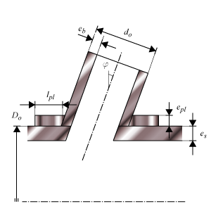
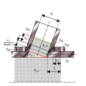
Stubon dimensions
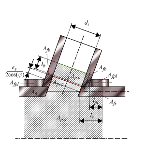
Stubon areas book
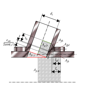
Stubon areas PCC (without gap)
Stubon areas NEW
Calculated Values
- Allowable Operating Stress header, branch and reinforcement – fs, fb, fpl
- Stress in the component at which it is still allowed (without failure) to use the component
- Allowable stress at 20 °C header, branch and reinforcement – fst, fbt, fplt
- Stress in the component at which it is still allowed (without failure) to use the component at testing condition
- Stress ratio branch/header – fb/fs, fbt/fst
- Ratio of operating stresses of the branch and the header. This ratio must be ≤ 1.
- Stress ratio reinforcement/header – fpl/fs, fplt/fst
- Ratio of operating stresses of the reinforcement and the header. This ratio must be ≤ 1.
- Required thickness header pipe and branch pipe – esr, ebr
- Based on the input, this is the calculated thickness that is required to sustain the loads. The nominal value should be smaller than the nominal design thickness.
- Reinforcement limit header direction – ls
- Length from the branch outside diameter to the end of the header reinforcement zone.
- Reinforcement limit branch direction – lb
- Length from the header outside diameter to the end of the branch reinforcement
- Material area header – Afs
- Cross-sectional area of header material between reinforcement limits.
- Material area branch – Afb
- Cross-sectional area of branch material between reinforcement limits.
- Material area reinforcement – Afpl
- Cross-sectional area of reinforcement material between reinforcement limits.
- Pressure area header – Aps
- Cross-sectional area with pressure in header between reinforcement limits.
- Pressure area branch – Apb
- Cross-sectional area with pressure in branch between reinforcement limits.
- Total pressure area – Ap
- Total cross-sectional area with pressure in header and branch between reinforcement limits.
- Pressure force – Fp
- Total force of the design pressure on the total pressure area.
- Maximum allowable pressure force – Fpmax
- Maximum allwable force of the design pressure on the total pressure area.
- Maximum Allowable Working Pressure – MAWP
- The maximum pressure at which the component can be used in operation. This value should be larger than the design pressure.
- Design margin – Pc/MAWP
- Ratio of the design pressure to MAWP
- Maximum Allowable Test Pressure – MATP
- The maximum pressure at which the component should be tested and survive.
- Tapering header and branch
- The tapering of the header and branch on connecting pipes is checked.
Scope errors
- Angle branch is out of scope (center line branch to header wall): required is 45° ≤ α ≤ 135°.
- This code determines a minimum and maximum branch angle.
- Inclined angle of the branch is out of scope: required is 0° ≤ φ ≤ 45°.
- This code determines a minimum and maximum branch angle.
- No reinforcement ring allowed for T > 300 °C
- This code determines that reinforcement area has to gained from header or branch.
- No reinforcement ring allowed for Pc > Pc_Max (see figure 8.3.6-1).
- This code determines that reinforcement area has to gained from header or branch.
- No reinforcement ring allowed for di/Di > 0.8
- This code determines that these branch connections no reinforcement is applicable.
- Branch connections with di/Di > 0.8 are not allowed in the creep range.
- This code determines that these branch connections are not applicable in the creep range.
Errors
- Can’t find material ‘MaterialName’ in database
- Material could not be found in database. Select an existing material name, or select another material via the material selection window.
- Insufficient wall thickness for header
- Wall thickness is insufficient to bear the applied loads. Increase the wall thickness.
- Insufficient wall thickness for branch
- Wall thickness is insufficient to bear the applied loads. Increase the wall thickness.
- Insufficient reinforcement area
- Reinforcement area is too small. Increase the reinforcement width or wall thickness of reinforcement, header or branch.
Warnings
- Tapering header in reinforced zone.
- Indicates tapering of header in reinforced zone.
- Tapering branch in reinforced zone.
- Indicates tapering of branch in reinforced zone.
Remarks
- Branch thickness is large (see 8.3.1), maximum used in calculation is twice the header thickness.
- This code determines for branches a maximum thickness.
- Branch thickness is large (see 8.3.1) for testing, maximum used in calculation is twice the header thickness.
- This code determines for branches a maximum thickness.