Input variables
Generic variables
These variables can be found in virtually all reports as input variables
- Location – Location
- The physical location of the component
- Test medium – Test medium
- The medium used to test the component
- Design Pressure – P
- Pressure assumed to be present in the component according to the design terms.
- Design Temperature – Td
- Temperature assumed to be present in the component according to the design terms.
- Material (header/branch)
- Name of selected material used for the construction of the component.
Specific variables
These variables are component specific.
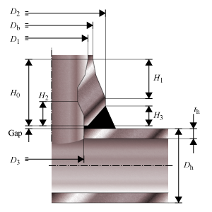
- Outside Diameter branch and header – Db, Dh
- Outside diameter of the part. The diameter runs from the outside of the wall to the opposite outside of the wall, through the center of the circle.
- Inside Diameter – D1
- Inside diameter at the top.
- Shoulder Diameter – D2
- Largest outside diameter.
- Diameter hole in header – D3
- Internal diameter opening between header and branch. Equal to the inside diameter at the bottom.
- Overall height branch – H0
- Height from top to bottom.
- Height at shoulder to branch – H1
- Height from the top to the largest outside diameter
- Height at inside beveled area – H2
- Height from the bottom to the smallest inside diameter.
- Height at welding area header – H3
- Available height at bottom for welding
- Gap between header and weldolet – Gap
- Clearance distance at bottom for welding
- Nominal Thickness Header – thn
- Thickness ‘as is’, meaning it is the design thickness taking into account corrosion and tolerance.
- Corrosion – A, Ah
- Amount of thickness that accounts for the possible effects of corrosion.
- Tolerance header – tolh
- Tolerance in thickness for production.
- Joint Efficiency header – Eh
- Effectiveness of the strength, depending on whether joints are seamless, welded, or expected to perform worse than the base material properties.
Weldolet dimensions
Calculated Values
- Minimum yield strength weldolet and header at 20 °C – Symin, Syh
- Stress in the component at which the component starts to plastically deform at 20 °C ambient temperature.
- Allowable Operating Stress weldolet and header – S, Sh
- Stress in the branch and the header at which it is still allowed (without failure) to use the component.
- Design factor – F
- Factor for the allowable stress when considering underthickness tolerance and maximum allowable depth of imperfections.
- Test design factor – Ft
- Factor for the allowable stress when considering underthickness tolerance and maximum allowable depth of imperfections at 20 °C ambient temperature.
- Allowable stress weldolet and header at 20 °C – St, Sht
- Stress in the branch and the header at which it is still allowed (without failure) to use the component at testing condition.
- Header reinforcement zone length – d
- Length from the branch centerline to the end of the header reinforcement zone.
- Active branch height – Hbact
- Equivalent height of the branch.
- Reinforcement thickness – te
- Equivalent reinforcement thickness in weldolet cross-sectional area.
- Branch reinforcement zone length – L
- Length from the header outside diameter to the end of the branch reinforcement zone.
- Required reinforcement area – AR
- The required cross-sectional area that reinforcement or excess thickness should provide.
- Stress ratio – S/Sh, St/Sht
- Ratio of the allowable stresses in the branch and the header.
- Reinforcement area header – A1
- Cross-sectional area of excess thickness header.
- Reinforcement area branch – A2
- Cross-sectional area of excess thickness branch.
- Reinforcement area of extra added area including weld areas – A3
- Cross-sectional area of extra reinforcement excess material.
- Total available reinforcement area – A
- The total available cross-sectional area from reinforcement and excess thickness. Sum of areas is corrected for stress ratio.
- Maximum Allowable Working Pressure – MAWP
- The maximum pressure at which the component can be used in operation. This value should be larger than the design pressure.
- Design margin – P/MAWP
- Ratio of the design pressure to MAWP
- Test pressure factor – FPt
- Factor for maximum test pressure
- Maximum Allowable Test Pressure – MATP
- The maximum pressure at which the component should be tested and survive.
- Required Test Pressure – Pt
- Required hydrostatic pressure for testing at any point in the piping system (paragraph 437.4.1)
Scope errors
- Temperature is out of scope: minimum temperature = -30 °C
- This code determines a minimum temperature.
- Temperature is out of scope: maximum temperature = 120 °C
- This code determines a maximum temperature.
- No header pipe dimensions specified.
- A header pipe is needed for the calculations.
Errors
- Can’t find material ‘MaterialName’ in database
- Material could not be found in database. Select an existing material name, or select another material via the material selection window.
- Insufficient wall thickness for header
- Wall thickness is insufficient to bear the applied loads. Increase the wall thickness of the header.
- Insufficient reinforcement area.
- Reinforcement area is too small. Increase the reinforcement area or thickness.